Quick Specs:
1985 production block 4 bolt main
377 cubic inches: 4.0” bore by 3.74” stroke
Scat rotating assembly with Icon pistons
9.5:1 compression forged pistons
AFR 195 Enforcer cylinder heads with spring Upgrade
64cc combustion chambers
Comp Cams Solid roller cam: 12-704-8
Comp Cams Solid roller lifter:
Comp Cams pushrod:
SpeedMaster shaft mounted rockers 1.5 ratio
Melling high volume oil pump
Erson fixed idler timing gear drive
MSD pro billet distributor
B&M 420 “Mega Blower” roots style supercharger
2 Holley Brawler 650 CFM carbs
A detailed parts list with links to vendors will be at the end of the article
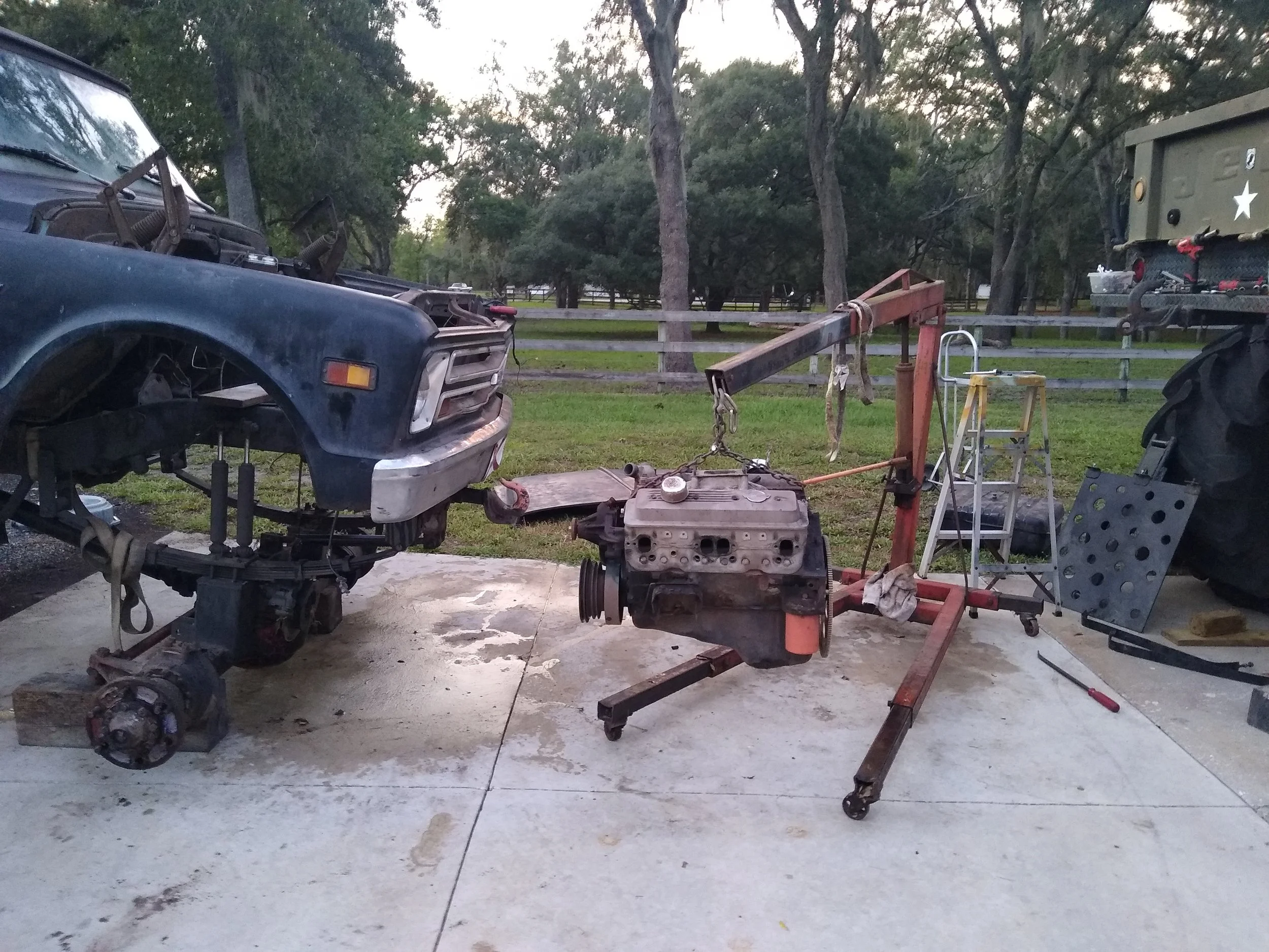
So after I spun a rod bearing, what was left is pictured below, in the SBC that was in my 68 C10, I needed a new engine. I had purchased a B&M 420 “Mega-Blower” a few months prior. This particular blower was made by B&M prior to Weiand (and eventually Holleys takeover) and is sized between a 6-71 and 8-71 blower, it has a unique mounting pattern that's specific to it only. But anyway, I decided that rather than doing a “rattle can rebuild”, a naturally aspirated build, or putting a junk yard motor in I would build a supercharged Small Block Chevy.
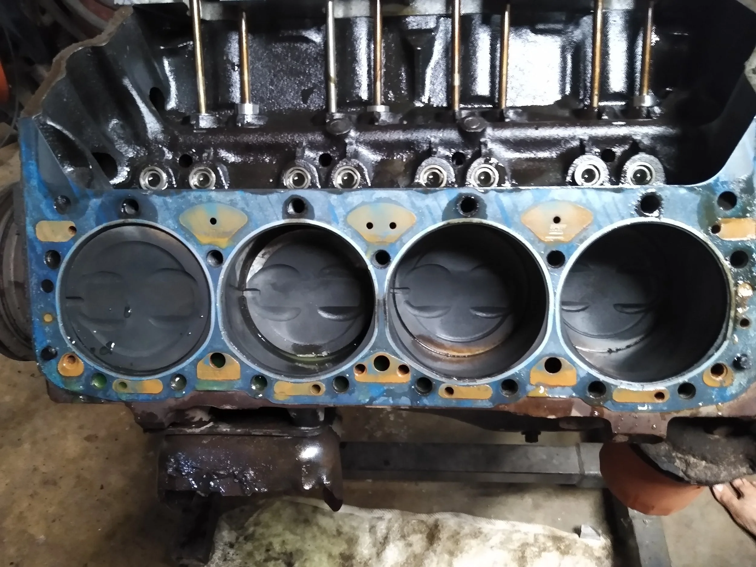
So after removing the blown engine from the truck and getting everything stripped down and cleaned it was time assess what I had. The engine was in the truck when I got it, and the previous owner knew nothing about the engine oher tah t had a gear drive timing set. upon pulling the oil pan we discovered that it was in fact a 4 bolt main, so next we checked the bore diameter and found it was standard bore with good cross hatching. After checking all the surfaces and bores I decided to not send it to a machine shop and just to a quick hone on the cylinder myself and save some money. I purchased a Brush Research ball hone and quickly cleaned up the cylinders and a few passes with a stone cleaned the decks up. Now that the engine was cleaned and the cylinders honed it was time for assembly.


First step was to assemble all the pistons and rods for each cylinder. I purchased a complete rotating assembly from CNC motorsports that included a Scat crank and rods as well as Icon forged pistons. the very first step was install the pistons on the rods, the kit came with free floating wrist pins held in with spiral locks. The locks proved to be a bit of a challenge at first but eventually we were able to get all of them by spreading the spiral a tad and then using needle nose pliers to spin the spiral into the groove; in the future I will probably purchase the correct tool for ease of installation. The next part of the piston assembly was to file fit all the rings, however we did not have to do this step, much to my surprise and dismay. It turns out there was such a wide tolerance in the manufacturing of the rings that by swapping rings around to different cylinders we were able to get each ring gap within 0.002” on the top and 0.003” second ring with no filing required. When we called the manufacturer he apologized and said that was the current state of manufacturing these days.
Final ring gap specs are:
Cylinder # Top Ring Gap Middle Ring Oil Ring
1 0.023" 0.024" 0.026" +
2 0.021" 0.024" 0.026" +
3 0.023" 0.027" 0.026" +
4 0.021" 0.027" 0.026" +
5 0.023" 0.027" 0.026" +
6 0.022" 0.024" 0.026" +
7 0.022" 0.026" 0.026" +
8 0.021" 0.027" 0.026" +

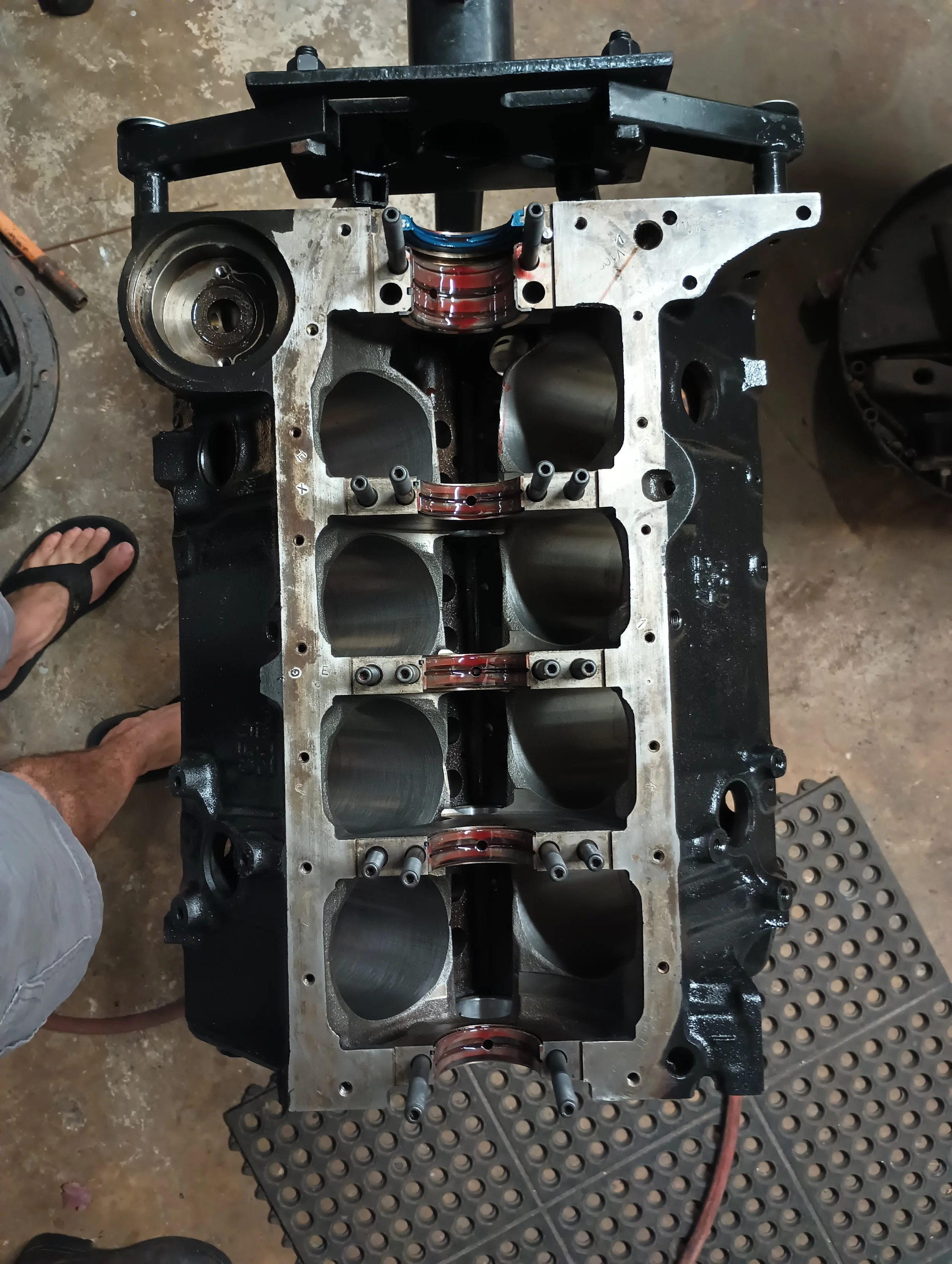
Once all the pistons and rods were assembled it was time to install the main bearings and crank, but first the main studs had to be installed. Once the studs were in, the upper main bearings were installed and lightly coated with assembly lube and the crank was dropped in. Main caps and lower bearings were next and the studs were torqued. Pistons were installed, and that is when we learned we had to clearance the block. all the crank throws on the passenger side of the block needed to be clearanced so the rods did not hit.


Next the cam was installed, and the gear drive timing set that was in the engine. Now this timing set was a floating idler style in which 2 idler gears float between the cam and crank gear and are held together with a tie bar. Using a zero offset bushing we decided to degree the cam in, so in went a lifter roller lifter pair that had been soaking in oil and a pushrod was placed on top of the lifter. Next a dial indicator was placed on the block and the stem on top of the pushrod. Our degree wheel was attached to the crank and the engine was spun over until the cam and pushed the push rod all the way up (max intake valve lift), once there the dial indicator was zero’ed. From there the engine was rotated until the dial indicator indicated 0.050” before max lift and the degree on the wheel was measured, then the engine was rotated the other way to 0.050” after max lift and the degree marked, averaging the two gave us the intake centerline. The procedure was repeated using 0.020” in case the ramp rates weren’t the same on intake opening and closing. After doing the procedure three times using each method it was determined the cam was ground 2 degrees advanced was around 112 degrees on the intake centerline. After switching out the zero degree bushing a 2 degree shim was used and set the intake centerline at 110 degrees.


Next came the cylinder heads, originally I planned to run the GM performance 113 heads that were on the engine to save some money (keep reading to find how trying to save money ended up costing me). However, the valves were small, they needed new springs, keepers, retainers and shims, and they wouldn’t clear the .575” lift of the cam. Plus these heads had dismal flow numbers, so after consideration I purchased AFR 195 Enforcer heads and had the springs upgraded to handle my cam. The 113’s were put on market place and sold the next day. The heads were secured to the block using studs and sealed with Fel-Pro head gaskets. Now it was time to check valve train geometry and pushrod length.

